Abstract
In the preceding post aes67_audio_notes(37) some basic and minimal AES67-based audio network was established and partially understood.
Using this knowledge and adding an additional piece of hardware, a MERGING+ANUBIS SPS PRO, the setup is extended towards a nice music playing experience.
This document contains the setup instructions and some experience collected with the various hardware components involved.
Network Setup
The following sections contain diagrams showing the topology of the intended audio network. Physical Connectivity refers to how actual wires are routed and Logical Connectivity shows how the audio streams are routed.
DHCP
IP addresses are listed here because they may later help identifying the components on the various screenshots. In practice, only 192.168.10.1 and 192.168.10.10 are assigned statically, whereas the remainder of addresses is dynamically assigned via DHCP. As far as I understand the AES67 design, it leverages multiple technologies including mDNS and IPv6 to allow operation even in the absence of a DHCP server on the audio network. It may be more difficult to get access to the components’ web interfaces in such a setup, though.
To setup an audio network with DHCP, you could adjust the following dnsmasq(8) configuration to your setup:
# /etc/dnsmasq.conf
domain-needed
bogus-priv
interface=enp1s0
listen-address=192.168.10.1
bind-interfaces
domain=masysma.org
dhcp-range=192.168.10.50,192.168.10.150,12h
Physical Connectivity
┌───────────────────────────────────────────────────────────────────────────┐
│                         Switch TP-Link TL-SG3216                          │
│                         192.168.10.10                                     │
└────────┬──────────────────┬──────────────────┬───────────────────┬────────┘
         │                  │                  │                   │
┌────────┴────────┐ ┌───────┴─────────┐ ┌──────┴─────────┐ ┌───────┴────────┐
│ PC Ma_Sys.ma 18 │ │ Audio Interface │ │ Left Speaker   │ │ Right Speaker  │
│ 192.168.10.1    │ │ MERGING+ANUBIS  │ │ Neumann KH 120 │ │ Neumann KH 120 │
│ enp1s0          │ │ SPS PRO         │ │ II AES67 W     │ │ II AES67 W     │
│                 │ │ 192.168.10.65   │ │ 192.168.10.113 │ │ 192.168.10.82  │
└─────────────────┘ └──┬──────────┬───┘ └────────────────┘ └────────────────┘
                       │          │
               ┌───────┴────┐ ┌───┴────────┐
               │ Headphones │ │ Microphone │
               └────────────┘ └────────────┘
The diagram shows which of the components are connected by wires. Notably, all AES67-enabled components connect to a common Ethernet network served by the switch. Note that the switch model was not chosen for its AES67-compatibility (it is not in any of the compatibility lists AFAIK) but due to the fact that it was available and allows for fanless switch operation.
If I had to buy a switch, I would probably attempt to use one managed switch for my home network and audio network and partition the switch in a way that a few ports (e.g. 5 ports) are reserved for audio usages. Cisco’s CBS350-xP-4X series (with x = 24, 48, 24NG or 48NG) look interesting, but also quite expensive. Also, for home usage the idle power consumption is always a concern.
Logical Connectivity
┌─────────────────┐        ┌─────────────────┐     ┌────────────┐
│ PC Ma_Sys.ma 18 │        │ Audio Interface ├─────┤ Headphones │
│ 192.168.10.1    │        │ MERGING+ANUBIS  │     └────────────┘
│ enp1s0          ├────────┤ SPS PRO         │     ┌────────────┐
│                 │        │ 192.168.10.65   ├─────┤ Microphone │
└─────────────────┘        └─┬─────────────┬─┘     └────────────┘
                             │             │
                  ┌──────────┴─────┐ ┌─────┴──────────┐
                  │ Left Speaker   │ │ Right Speaker  │
                  │ Neumann KH 120 │ │ Neumann KH 120 │
                  │ II AES67 W     │ │ II AES67 W     │
                  │ 192.168.10.113 │ │ 192.168.10.82  │
                  └────────────────┘ └────────────────┘
From a logical point of view, the Audio Interface is the central component. Although it is connected by only one Ethernet port, it offers two virtual inputs to enable stereo audio to be sent from the PC for playback to the speakers. Also, it offers three virtual outputs: One for the PC to process the Microphone input (e.g. for a virtual phone conference or such) and two for the streams to the left and right speakers.
The advantage of routing all of the audio through the interface compared to e.g. directly creating the speakers’ streams on the PC is that by connecting the setup this way, the Audio Interface can be used for controlling the speakers volume, mute/unmute or even apply DSP effects if wanted.
AES67 Configuration
After having established the general idea about how the various hardware components should be connected from a logical point of view, some configuration is needed on all of the AES67-enabled components to create, route and attach the audio streams correctly.
Low-Level Software Requirements
Software requirements concern the host PC. As already noted in aes67_audio_notes(37), there are multiple ways to go about the software side.
My currently used and recommended setup is to make use of the free MERGING+RAVENNA kernel module in conjunction with the free aes67-linux-daemon.
Build instructions for MDPC 2.0 can be found in these repositories:
A dedicated Ethernet interface for audio usage is recommended. Compile and install both of these dependencies and then continue to configure the components.
Software Configuration
On the PC side, configuration can be done through the aes67-linux-daemon web interface and JSON config. An example JSON config is supplied alongside the build instructions. Important configuration pages for the web interface are depicted in the following.
A helpful document in understanding the meanings of the parameters is the Practical Guide to AES67 which can be found here: https://www.ravenna-network.com/your-practical-guide-to-aes67-part-2-2/.
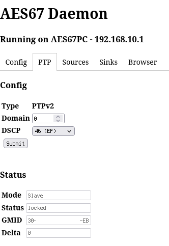
DSCP stands for Differentiated Services Code Point (aka. DiffServ) and refers to the way in which the IP frames are tagged for Quality of Service. EF stands for Expedited Forwarding. DSCP=46 (EF) is the recommended configuration for RAVENNA. PTP is the highest priority traffic from an audio network point of view.
The domain number is supposed to be 0. Note that the IPv4 multicast address is dependent on the domain number, cf. https://en.wikipedia.org/wiki/Precision_Time_Protocol.
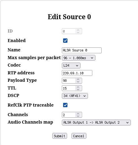
To send audio streams to the interface, create a two-channel source on the PC. Important parameters are as follows:
- Max samples per packet=96. Technically this value encodes how many samples are sent in a single IP packet. At 48 kHz we need 48000 samples per second and channel that means 96000 samples per second. With a target of one packet every 1ms this amounts to 96 samples per packet. Interestingly, choice 96 seems to be also OK for operation at 88.1 kHz although it would logically amount to 88.1 * 2 = 176.2 ~ 172 samples per packet for 1ms packet sending intervals. Sometimes the configuration options in AES67-related systems are “normalized” to assume 48 kHz, I don’t know whether this is the case here, too, though. From practical testing, I think one is not supposed to mess with this value and leave it at 96 in most cases, because it just doesn’t work when you chose anything else :)
- Codec=L24. L16 is to mean Linear PCM with 16 bit and L24 Linear PCM with 24 bit. However, this is not the whole truth because only certain combinations are required to work per the AES67 standard, cf. table below. If a choice called AM824 is offered, this is a special codec used to transparently transport AES3 data. it is not a recommended choice for pure AES67 network operation.
| Sample Rate/kHz | Works with L16 | Works with L24 |
|---|---|---|
| 44.1 | yes | not necessarily |
| 48 | yes | yes |
| 88.2 | not necessarily | yes (?) |
| 96 | not necessarily | yes |
- RTP address=239.69.1.10. I assign a value with 239.69.x.x with the
last two
xequal to the device’s IP address (optionally incrementing the value if multiple streams are to be offered). I don’t know if this is really the best practice, but it seems to work. - Payload Type=98 - may stay at the default. See https://support.dhd.audio/doku.php?id=aes67:configure_tx_streams for some explanation about the payload type. It seems it may take any value from 96..127 such as long as all participants agree to use the same value.
- TTL=15 - may stay at the default. Large TTL may not make sense due to latency considerations.
- DSCP=34 (AF41) - recommended per https://www.ravenna-network.com/your-practical-guide-to-aes67-part-2-2/. AF41 is one below EF in priority.
To complete the software configuration, after having setup the hardware, it is also possible to create a Sink for the aes67-linux-daemon in order to record audio inputs from the interface, e.g. a microphone.
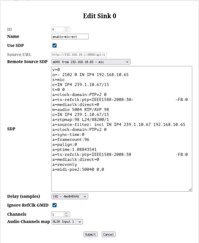
I don’t know what is meant with the Delay (samples) setting here, but the smallest choice of 192 seems to work fine here.
Hardware Configuration (Screenshots)
The MERGING+ANUBIS can be configured through its web interface. This consists of two parts: There is a webbrowser-based mirror of the GUI of the device itself, allowing for remote control of the standard features. Additionally, when clicking on the sample rate in the web interface, an Advanced page is opened.
This offers all the necessary configuration options to setup connections without the application Aneman (which is Windows-only). Aneman seems to be the documented/recommended way to setup AES67 connections, but the advanced pages worked just fine for my use cases and thus the need for Aneman was bypassed, enabling a Linux-only setup.
ANUBIS General Config
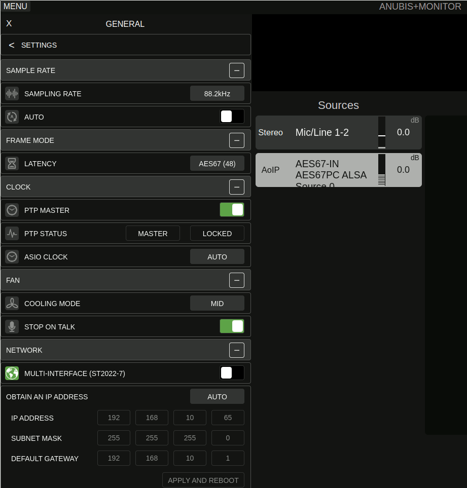
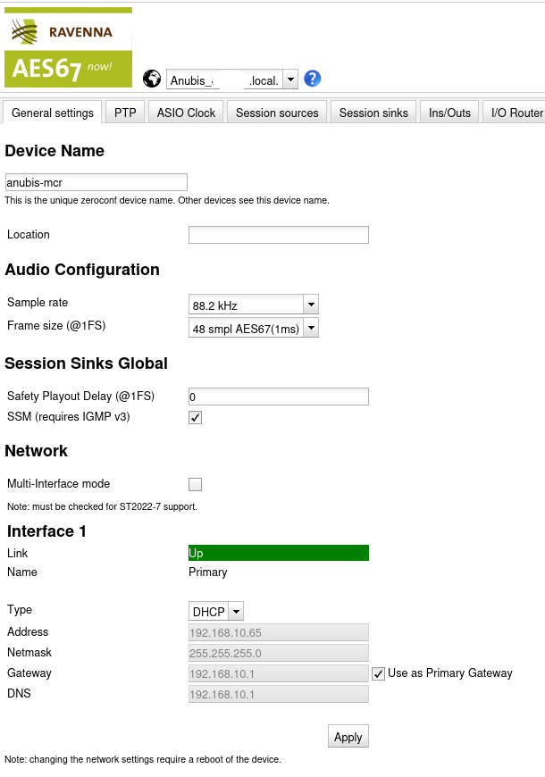
On the General Settings page, the important settings are Sample rate and Frame size. I chose to configure the sample rate to 88.2kHz across the entire setup. Frame size of 48 seems to work fine. I don’t know its exact meaning, but the idea seems to be to establish a common understanding of “1ms” packet interval across the network.
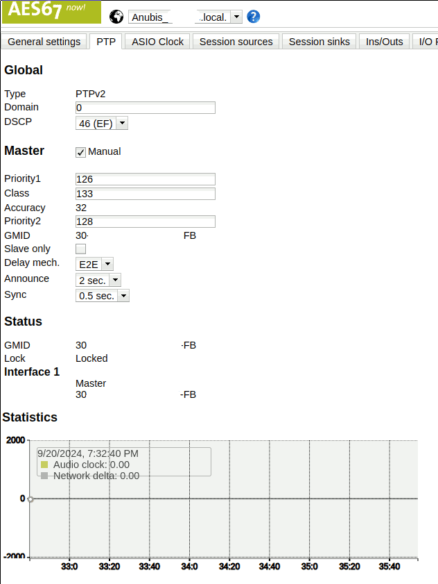
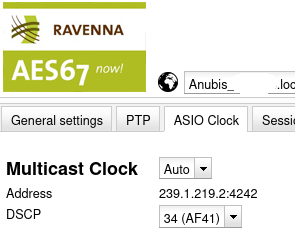
In my setup, I configured the MERGING+ANUBIS to act as the master clock. Given that it is a dedicated networked audio hardware and contains a battery-backed RTC it should make for a good reference for all of the audio purposes. As far as I understand, this restricts the ability to switch the sample rate of the MERGING+ANUBIS to follow what is configured in ALSA, though. It may make sense to explore making the PC the master clock to get access to that feature. This is not relevant when playing back through the speakers because these require a fixed sample rate, but it could be an interesting option for bit-perfect playback to headphones in the future. For now I live with the fact that everything is resampled to 88.2kHz.
The recommended settings for the timings per the Practical Guide to AES67 are sync time = 0.5s (alternatively 1 or 2 seconds) and announce interval = 2s with delay mechanism=E2E. I find it confusing that this are not the default values, but it seems to work fine with either the default 0.125s sync time or the recommendation of 0.5s. In general I prefer to use the longer latencies because my use case is not overly critical wrt. latency and I prefer to have some latency error margin over the maximum performance here.
The priority settings are relevant when there are multiple (e.g. redundant) choices for master clocks on the network. In my setup there is only the MERGING+ANUBIS as master and hence the default values may be used without modifications.
ANUBIS Audio Streams
The configuration of audio sources and sinks consists of three steps:
- Creating the necessary sources. This is what the MERGING+ANUBIS is going to “output” via network. It may then be be consumed on either the PC or the speakers.
- Creating the necessary sinks. This is what the MERGING+ANUBIS receives as “input” via network.
- Creating the necessary links between source and sink. It is important to not link network sources to network sinks directly here because this bypasses all of the processing on the MERGING+ANUBIS including essential stuff such as volume control and mute.
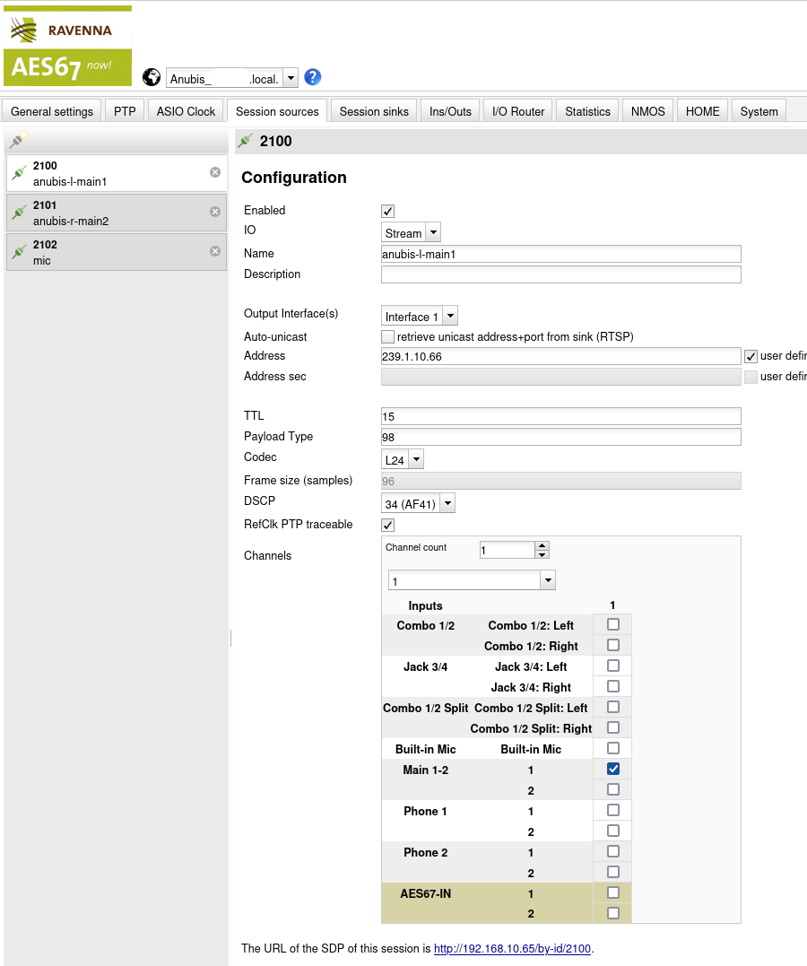
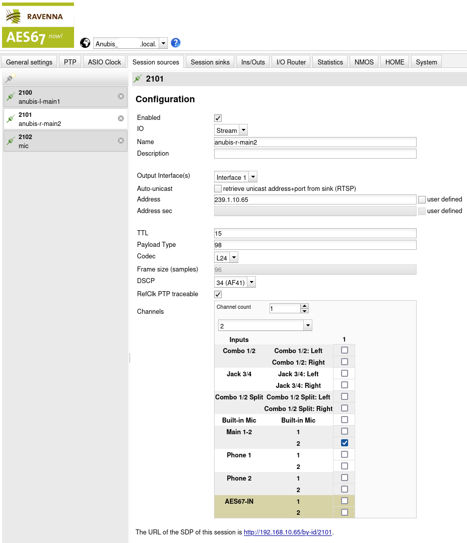
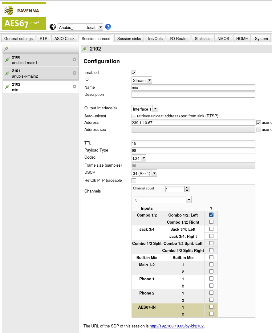
Three sources are created:
| Source | Name | Address | Description |
|---|---|---|---|
| 2100 | anubis-l-main1 | 239.1.10.66 | Stream to send to left speaker |
| 2101 | anubis-r-main2 | 239.1.10.65 | Stream to send to right speaker |
| 2102 | mic | 239.1.10.67 | Microphone stream to send to the PC |
TTL, Payload Type, Codec and DSCP are all configured as before. Although it may not be necessary, I like to keep these values aligned throughout the entire setup.
The setting under Channels is used to tell MERGING+ANUBIS what this channel corresponds to:
| Source | Name | Channels | Idea |
|---|---|---|---|
| 2100 | anubis-l-main1 | Main 1-2: 1 | Map the speakers to the “main” output |
| 2101 | anubis-r-main2 | Main 1-2: 2 | of the ANUBIS e.g. for volume control. |
| 2102 | mic | Combo 1/2: Left | This is the hardware port of the Mic. |
This way, dedicated streams are created for the left and right speakers. This is required by the hardware because Neumann KH 120 II AES67 W can only attach to the first channel in a given stream and hence there must be one stream per speaker that is intended to play anything different. In this case this means a left and right channel for stereo material.
Since mic is directly linked from the hardware port,
this source directly corresponds to what is received via the hardware
making the unfiltered mic stream available to the PC. Gain and other
hardware-centric microphone settings are of course applied.
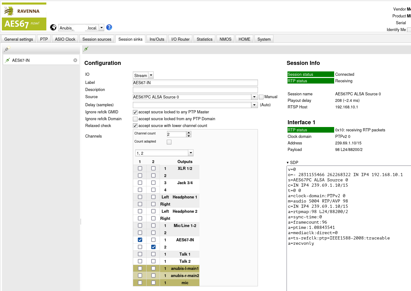
For the creation of the Sink it is possible to select the ALSA Source 0 from the dropdown menu. The contained channels are mapped to a network input called AES67-IN on the MERGING+ANUBIS. The name here is arbitrary (like with the sinks) and used to indicate this input in the MERGING+ANUBIS user interface.
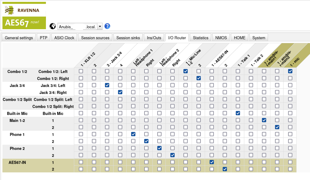
To assign audio streams for the MERGING+ANUBIS, page I/O Router is used.
On the vertical axis, you can find all available inputs whereas on the horizontal axis there are all possible outputs. Note that this can be slightly confusing, because while it is clear that Built-in Mic is actually an input, this is not so obvious for Phone 1 (a headphone) because why is a headphone an input?
AFAUI the idea here is that mixes appear as inputs here as well. I.e. there is the Main 1-2 which is the “main mix” (e.g. button “A” on the MERGING+ANUBIS) or Phone 1 which is the mix assigned to the first headphone button (“1”) on the MERRGING+ANUBIS. Now this routing page allows you to send this mix to arbitrary physical or AES67 outputs. E.g. the Phone 1 mix is sent to the first headphone jack (Left - Headphone 1 and Right) but the MERGING+ANUBIS is flexible and would also allow you to send it to the second headphone jack instead (or even in addition or …!)
The following assignments are “trivial” in the sense that they assign the inputs in a way that directly corresponds to the same counterpart on the output side:
- Assign AES67-IN to none of the physical or networked outputs but only to “itself”. This allows selecting it as a source in the MERGING+ANUBIS UI.
- Assign Phone 1 to Left - Headphone 1 and Right. This maps the virtual Phone 1 mix to the physical connector for the first headphone (makes sense I think).
- Assign Combo 1/2 Left to 1 - Mic/Line 1-2 and Combo 1/2 Right to 2. This allows the microphone to be selected as an source in the MERGING+ANUBIS UI.
The following assignments are performed in addition to populate the AES67 outputs:
- Assign Combo 1/2: Left to 1 - mic. This streams the microphone audio to the PC.
- Assign Main 1-2: 1 to 1 - anubis-l-main1. This streams the first channel of the main mix to the left speaker.
- Assign Main 1-2: 2 to 1 - anubis-r-main2. This streams the second channel of the main mix to the right speaker.
To complete this overview about the setup, the following pictures show the configuration on the speaker side.
Left Speaker
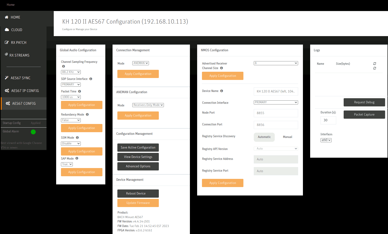
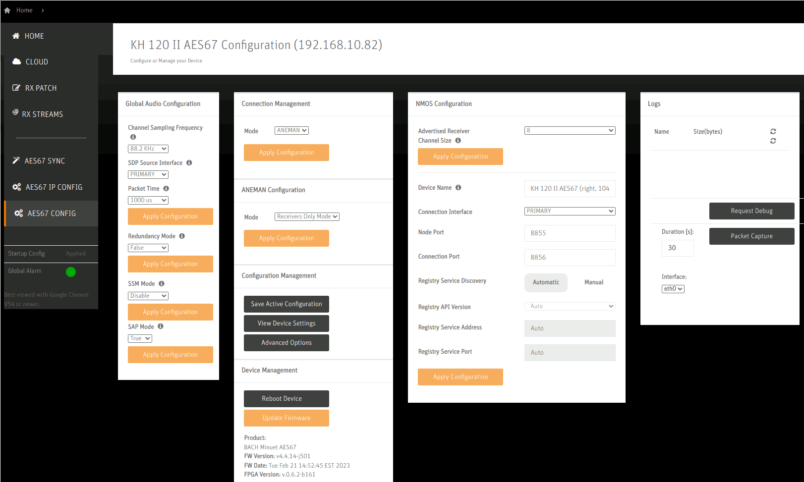
On the AES67 Configuration page, the chosen sample rate 88.2kHz and a packet time of 1ms (=1000us) is set.
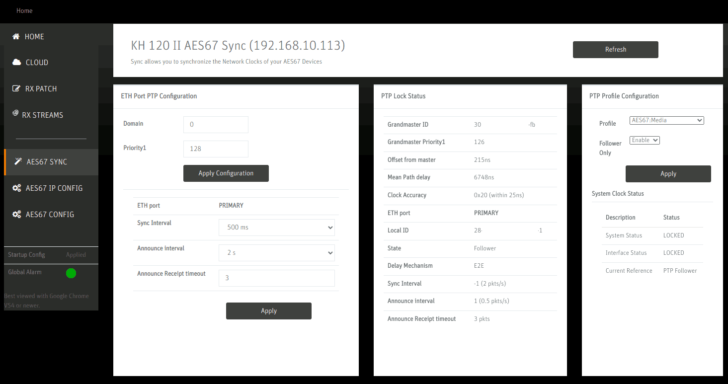
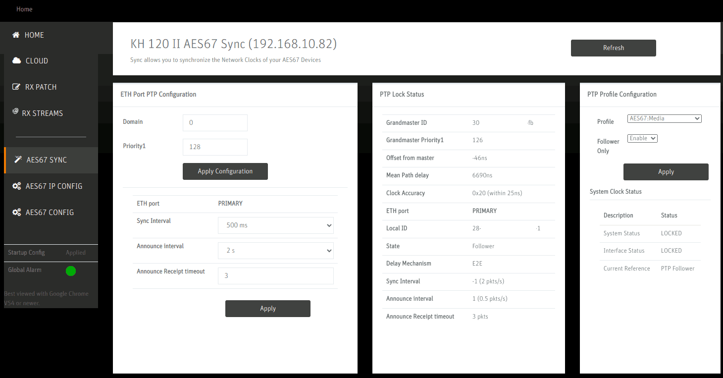
On the AES67 Sync page, the status of the synchronization can be checked. Profile is set to AES67: Media and Follower Only: Enable disables the speaker’s integrated master clock feature. On the left side, Sync Interval, Announce Interval and Announce Receipt timeout are configured to the recommended values per the Practical Guide to AES67.
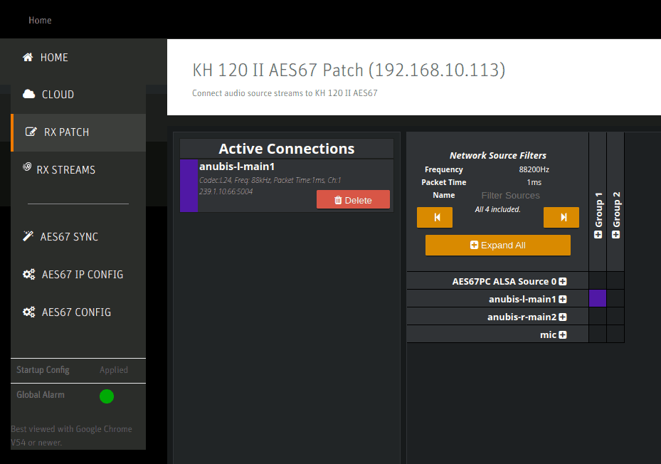
The RX patch panel shows all of the detected sources on the right side. By selecting a square and clicking Patch it is assigned and becomes one of the Active Connections. Note that one must not select AES67 PC ALSA Source 0 here since (1) it would only ever assign the left channel (even on the right speaker) and (2) it bypasses the MERGING+ANUBIS’ volume control causing the speakers to play at full loudness. Such a setup is only sensible if no MERGING+ANUBIS is available or there is another reason to prefer software-based volume control (which must then be enabled in ALSA or the PC application).
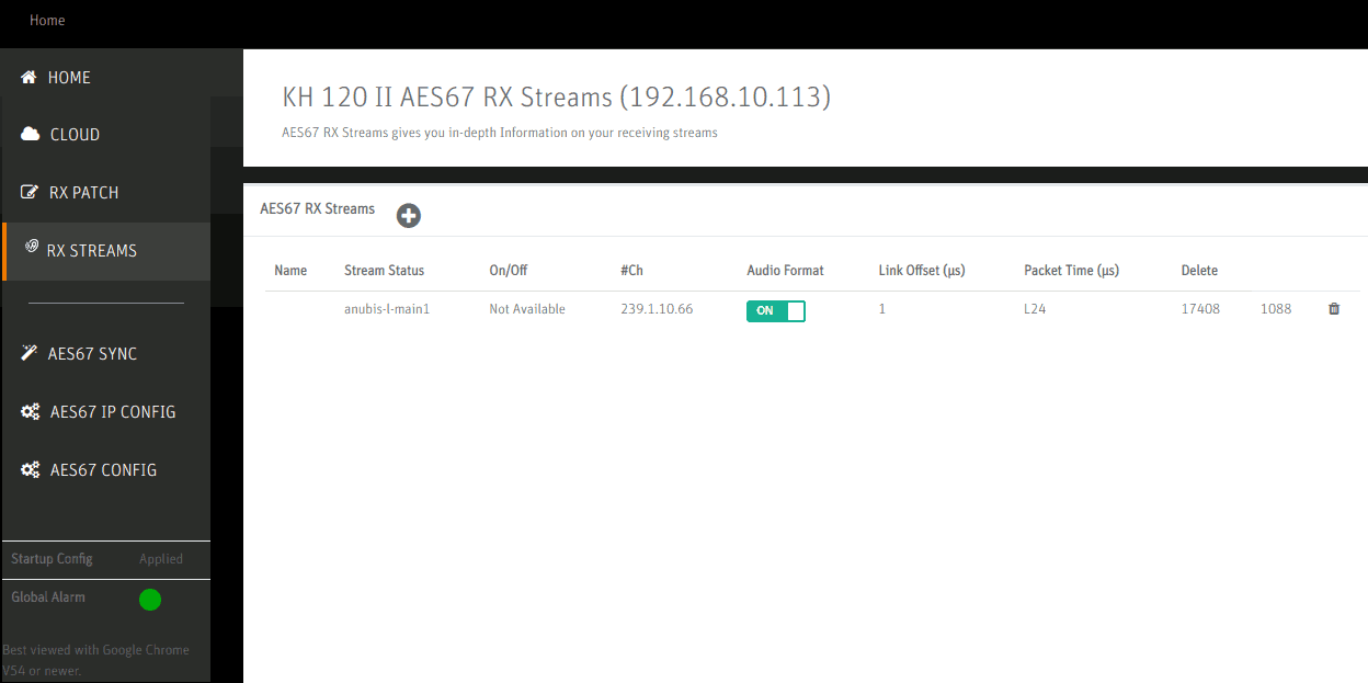
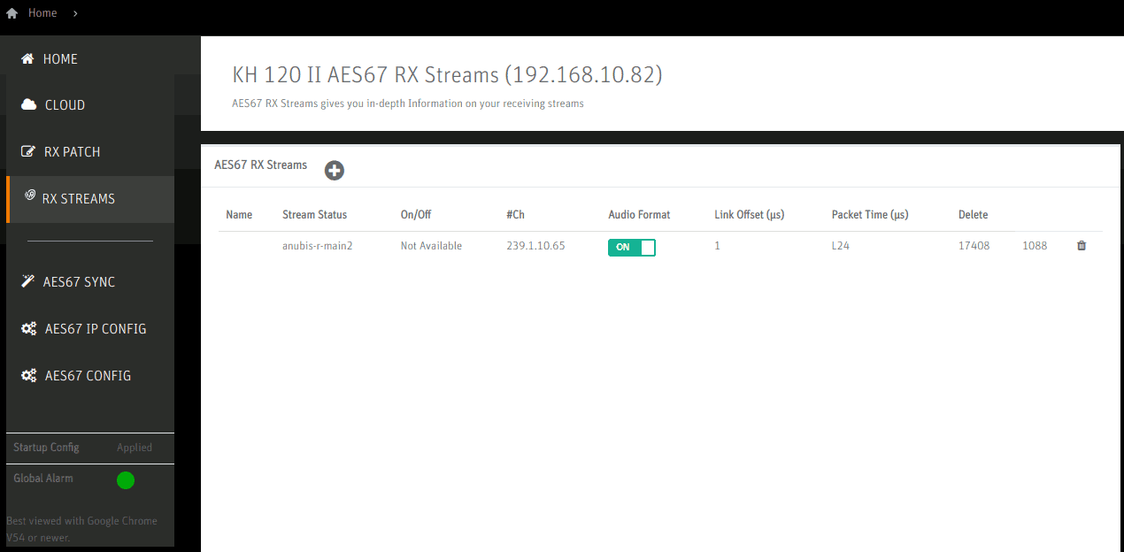
The RX Streams page is populated automatically but it allows checking whether some values have been propagated correctly e.g. one can recognize the configured codec L24 under Packet Time.
Right Speaker
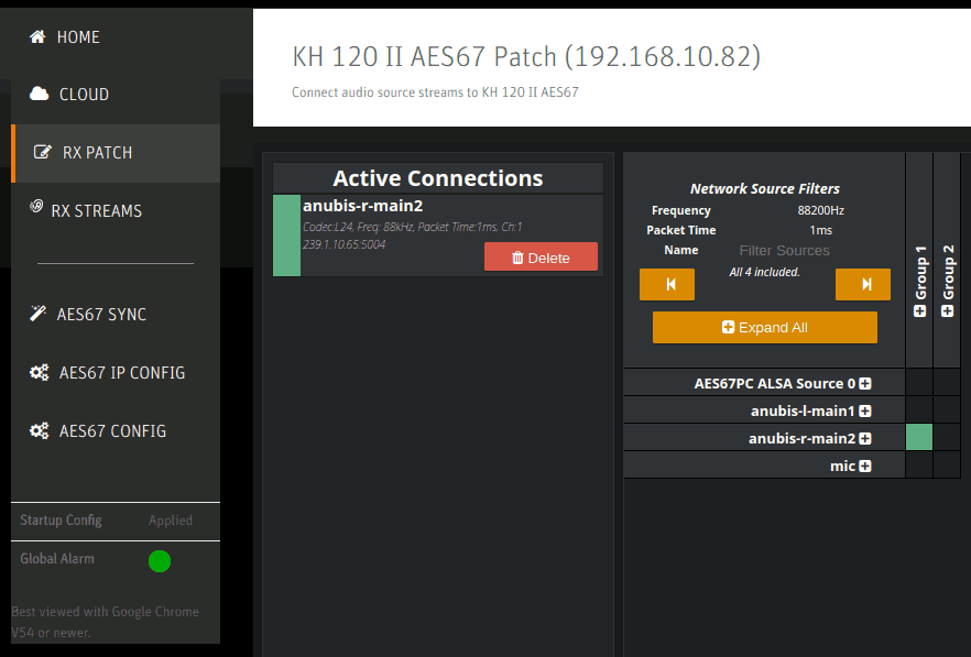
Configuration of the Right speaker is similar, but notably using a different channel mapping on the RX Patch page.
Optional Network Switch QoS Settings
I have long run the setup without any particular Network Quality-of-Service (QoS) configuration. For small setups it may thus not be needed to configure this. This section shows what I understand to be the correct settings per the Practical Guide to AES67 such that it might even work for larger setups.
The QoS configuration must prioritize as follows:
- PTP traffic (46/EF) at highest priority
- Audio traffic (34/AF41) at higher-than-normal priority
- All other traffic at normal priority
Switches prioritize traffic by maintaining multiple queues of packets. The recommended scheduling is to have higher-priority queues have absolute priority over lower-priority ones (i.e. an “unfair” scheduling). This is known as strict policy forwarding.
The exact way how a given switch indicates these parameters may differ between models. Below you can find the settings screens for the TL-SG3216 used in my setup.
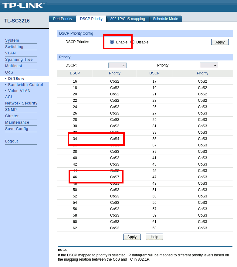
The DSCP Priority based scheduling must be enabled (upper part of the screen).
In the table, values 34 (AF41) and 46 (EF) are assigned their own dedicated levels (higher CoS means higher scheduling priority). The choice of CoS4 and CoS7 is rather arbitrary here: CoS7 is the highest value offered and by default CoS4+CoS5 and CoS6+CoS7 are mapped to the same queue such that by using CoS4 and CoS7 this already assigns to different queues by default.
Although I am not sure if this is really necessary, I downgraded all of the other DSCP to at least CoS3 (or kept it lower if that was the default). AFAIU this shouldn’t really matter since as this is a dedicated audio network, other traffic does not indicate any DSCP prioritization, but by setting it as shown (many clicks, maybe next time do it over SSH…) it is strictly enforced that AF41 and EF get a higher priority than the remainder of traffic.
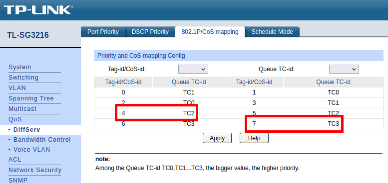
Here, the defaults could stay in place. All PTP traffic goes to TC3, audio traffic to TC2 and all other traffic goes to queues TC0 and TC1. Higher queue ID means higher priority as shown in the note near the bottom of the screen.
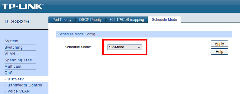
The Schedule Mode is set to SP-Mode which corresponds to the strict policy forwarding recommended for AES67 operations.
Overview of Values to configure for a Working Setup
| Keyword | Value | Adjust to your setup? |
|---|---|---|
| PTP Domain | 0 | no |
| PTP DSCP | 46 (EF) | no |
| Max samples per packet | 96 | no |
| Codec | L24 | Use L24 except for sample rate 44.1kHz (-> L16) |
| RTP address | 239.69.1.10 | Assign one address per stream! |
| Payload type | 98 | no |
| TTL | 15 | no |
| Audio DSCP | 34 (AF41) | no |
| Sample Rate | 88.2kHz | yes if wanted |
| Frame size @1FS | 48 smpl | no |
| PTP Delay Mechanism | E2E | no |
| PTP Sync Time | 0.5s | no |
| PTP Announce Interval | 2s | no |
| Timeout | 3s | no |
High-Level Software Interactions: ALSA, PipeWire and MPD
In order to play music with at most (typically exactly) one sample rate conversion across the playback path, the Music Player Daemon (MPD) is configured to access the ALSA “soundcard” for AES67 output directly.
The Easy Way: Alternating Access between MPD and PipeWire
In this setup, MPD might be configured as shown below:
# mpd.conf
resampler {
    plugin      "libsamplerate"
    type        "0"
}
audio_output {
    type            "alsa"
    name            "AES67"
    device          "hw:CARD=RAVENNA,DEV=0"
    allowed_formats "88200:24:2"
    auto_resample   "no"
}
This causes MPD to exclusively access the ALSA device, making it
unavailable to other applications while playing music. Specifically, no
software-side mixing occurs. The configuration of
allowed_formats ensures that the sample rate is never
changed to anything except 88200Hz, causing the PC to stay in sync with
the audio interface.
MPD is not the only audio source on a desktop system, though. When
using web browsers or games, these often attempt to play audio through
PulseAudio. Nowadays, PulseAudio is often not actually the backend but
rather emulated through a component like pipewire-pulse
with the actual sound server tasks being handled by PipeWire.
It is important to establish that PipeWire never attempts to change the sample rate of the output device because then the PC would lose connectivity to the MERGING+ANUBIS. AFAIU this is due to MERGING+ANUBIS being the master clock and could be addressed by moving the master clock to the PC, but for now assume it is that way.
To ensure this, add the following file to
/etc/pipewire/pipewire.conf.d and
/etc/pipewire-pulse.conf.d (it is included in the
lp-aes67-linux-daemon repository and installed by the
package generated from it).
# /etc/pipewire/pipewire.conf.d/91-masysma-sampling.conf

# https://man.archlinux.org/man/extra/pipewire/pipewire.conf.5.en
context.properties = {
    default.clock.rate          = 88200
    default.clock.allowed-rates = [ 88200 ]
    default.clock.max-quantum   = 8192
    default.clock.quantum-limit = 8192
}

# https://wiki.archlinux.org/title/PipeWire#Sound_quality_(resampling_quality)
stream.properties = {
    resample.quality = 10
}
This helps against PipeWire changing the sample rate of the output device to its default of 48kHz.
When setting up the system like this, the access to the hardware ALSA
device is still exclusive. Hence either PipeWire or MPD may access it,
usually it is “first come first serve”. Although MPD closes the device
to allow it to be used by other applications while it is not playing
music, this is usually not enough for PipeWire to automatically switch
to it then. What happens instead is that unless PipeWire is laboriously
restarted
(systemctl stop pipewire-pulse && systemctl stop pipewire && systemctl stop pipewire
or such), it just sends its audio output to any other audio device which
could e.g. be the integrated Audio or GPU.
There are two ways to work around this issue:
- Setup MPD to use PipeWire. I didn’t explore this but the most difficult part here may be to tell PipeWire to leave alone and “just” copy the audio data to ALSA here.
- Split the ALSA device to be used by MPD and PipeWire in parallel. This has a higher chance of leaving the audio data untouched and although it is also complex, this seems easier to me since ALSA configuration is mostly static whereas PipeWire has some static and some dynamic run-time configuration parts (and also at least three components to consider: PipeWire, Wireplumber and PipeWire-Pulse).
The Complicated Way: Splitting up an ALSA Device
The following section describes how I setup a variant of the second option mentioned at the end of the previous section.
- DANGER
- All of the information on this page is experimental. While trying to get the configuration right, I went through multiple kernel panics (10 times or so) when having configured buffer values wrongly. This is very sensitive. Although the latency is likely to cause distorted audio, I recommend to test this in a VM first and once you get stable (even if distorted) output, move the config to the main system. In my case an additional USB Ethernet adapter to “attach” the VM to the audio network and the creation of a TEST input in the MERGING+ANUBIS helped to play back the audio from the VM.
The approach is as follows:
- Extend the AES67 Daemon config to map exactly 8 channels to ALSA. Note that tests with channel numbers different from 2 and 8 caused all sorts of issues from Kernel Panic on the PC to the stream not being receivable on the MERGING+ANUBIS. Hence always use 8 or 2…
- Create an ALSA config with two (virtual) PCM devices (sink_1, sink_2) with two channels each mapping them to channels 0/1 and 2/3 of the RAVENNA ALSA device.
- Configure MPD to use sink_1 and PipeWire to use sink_2
- Receive both of the associated AES67 streams on the MERGING+ANUBIS and thus allow quick switching between (or even mixing together) these PC-originating audio sources.
Extending the AES67 Daemon Config
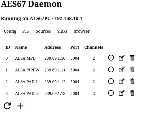
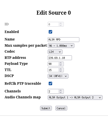
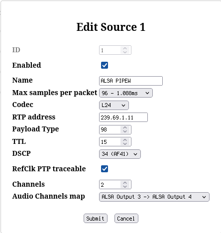
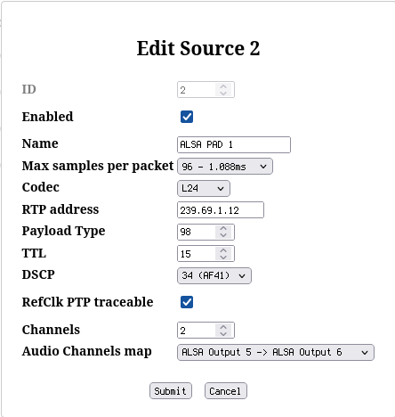
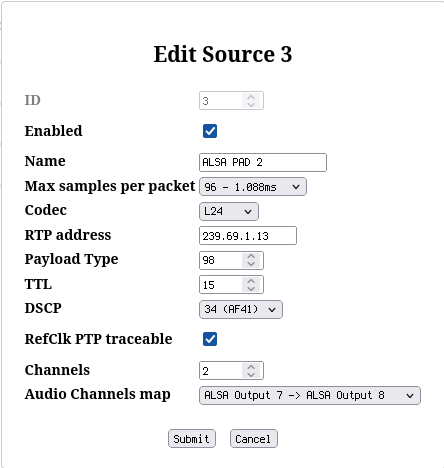
Instead of one AES67 output with two channels, create four such outputs as shown in the screenshots. Note that instead of naming them just ALSA Source 0..3, this time some useful names were assigned:
- MPD to indicate that this is the MPD audio output
- PIPEW to indicate PIPEWIRE source
- PAD 1 and PAD 2 to indicate that these exist for padding to exactly 8 channels.
Create an ALSA Config
This turned out to be the most complicated part due to wrong buffer sizes easily causing whole system lockups (Kernel Panic). The resulting config is thus not completely scrutinized. There may be some optimizations possible, but I left it in the state once it was working OK-ish.
You can also find this file in the repository
lp-aes67-linux-daemon.
# /etc/alsa/conf.d/98-masysma-aes67.conf

pcm_slave.ravenna_card {
    pcm         "hw:CARD=RAVENNA,DEV=0"
    channels    8
    rate        88200
    format      S24_3LE

    # DANGER, system halts when configured wrongly!
    period_time 0
    period_size 96
    buffer_size 9216
}

pcm.source_1 {
    type        dsnoop
    ipc_key     0x11111
    slave       ravenna_card
    bindings {
        0 0
    }
}

pcm.sink_1 {
    type plug
    slave.pcm {
        type    dshare
        ipc_key 0x11111
        slave   ravenna_card
        bindings {
            0 0
            1 1
        }
    }
}

pcm.sink_2 {
    type plug
    slave.pcm {
        type    dshare
        ipc_key 0x11111
        slave   ravenna_card
        bindings {
            0 2
            1 3
        }
    }
}
The most difficult part about coming up with this config file were the settings of the parameters below DANGER. I try to provide my understanding in the following paragraphs. Please note that as of this writing, I am not sure whether this is correct. I welcome corrections being sent to my e-mail address!
In ALSA, there are basically five parameters that can be configured here:
| Parameter | Unit | Summary |
|---|---|---|
period_time |
us | Interval at which buffer transfers are performed |
period_size |
samples | Unit of transfer measured in samples |
buffer_time |
us | Maximum time of audio playback to keep in the buffer |
buffer_size |
samples | Buffer size to allocate measured in samples |
periods |
1 | = buffer_size / period_size |
AFAIU, any two of these parameters are sufficient to compute the
remainder. The relation between sizes and times is a bit strange,
because documentation I have found online seems to suggest that the
sizes are to be measured in bytes but looking at the dmesg
outputs of the kernel driver suggests that in case of AES67 these
parameters are both actually measured in samples rather than bytes. On
Github it was confirmed that for this driver the figures are in
samples: https://github.com/bondagit/aes67-linux-daemon/issues/174,
The conversion between samples and bytes is as follows: 1 sample = 8 channels x 24 bit encoded as 3 bytes = 24 bytes.
The conversion between time and samples is via the sample rate: 1 sample = 1 / (88200s) ~ 11.3379us.
From the AES67 configuration, I know that the nominal packet time is
1ms or more precisely (max, and I think also actually) 96 samples per
packet which means 96 / 88200 ~ 1088.4354us per packet. In the
dmesg output of the driver it tells
Base period set to 1088435 ns hence this seems to really be
the time value to use for period_time with the
corresponding period_size of 96 samples (= 2304 bytes). In
any case it makes sense to configure 96 samples for minimum latency
here, although I would have liked to set it a little higher, other
values I tried seemed to be rejected (or corrected to 96) by the
driver.
The driver internally seems to limit the number of periods to 96,
cf. this excerpt from audio_driver.c:
static struct snd_pcm_hardware mr_alsa_audio_pcm_hardware_playback =
{
    /* ... */
    .rate_min =         44100,
    .rate_max =         384000,
    .channels_min =     1,
    .channels_max =     MR_ALSA_NB_CHANNELS_MAX,
    .buffer_bytes_max = MR_ALSA_RINGBUFFER_NB_FRAMES * MR_ALSA_NB_CHANNELS_MAX * 4,
    .period_bytes_min = MR_ALSA_NB_FRAMES_PER_PERIOD_AT_1FS * 2 * 3,
    .period_bytes_max = MR_ALSA_NB_FRAMES_PER_PERIOD_AT_1FS * 8 * MR_ALSA_NB_CHANNELS_MAX * 4,
    .periods_min =      2, // min number of periods per buffer (for 8fs)
    .periods_max =      96, // max number of periods per buffer (for 1fs)
    .fifo_size =        0
};
I went with the maximum number of periods (96) and configured it in
form of the buffer_size measured in frames: 96 periods x
period size 96 = 9216 samples (= 221184 bytes or ~104ms).
Check that the parameters are effective by querying the active
parameters from
/proc/asound/RAVENNA/pcm0p/sub0/hw_params:
access: MMAP_INTERLEAVED
format: S24_3LE
subformat: STD
channels: 8
rate: 88200 (88200/1)
period_size: 96
buffer_size: 9216
Useful links regarding the understanding of the ALSA configuration:
- https://github.com/bondagit/aes67-linux-daemon/issues/174
- https://bootlin.com/blog/audio-multi-channel-routing-and-mixing-using-alsalib/
- https://askubuntu.com/questions/106186/how-to-split-7-1-soundcard-outputs-to-
- https://www.sabi.co.uk/Notes/linuxSoundALSA.html
Useful links regarding whether something similar could also be done with Pipewire instead. It may become interesting in the future. Still, from a preliminary look it seems that it would (1) not improve latency and (2) maybe even require figuring out just the same parameters as needed for ALSA, just specified in a different syntax:
- https://gitlab.freedesktop.org/pipewire/pipewire/-/wikis/Virtual-Devices#examples
- https://wiki.archlinux.org/title/PipeWire#High_latency_with_USB_DACs_(e.g._Schiit_DACs)
- https://gitlab.freedesktop.org/pipewire/pipewire/-/issues/57
- https://gitlab.freedesktop.org/pipewire/wireplumber/-/issues/400
Configure MPD to use sink_1
This was a little involved because although MPD would attempt to open the sink, it would just silently pause the playback again without any reasonable indication what was wrong. Enabling the logging in MPD helped to identify the issue somewhat. What helped more was to get the remainder of the ALSA config right, then MPD started working, too…
# mpd.conf

# useful for debugging if MPD doesn't work:
#log_file               "/tmp/mpd.log"
#log_level      "info"

audio_output {
    type        "alsa"
    name        "AES67s1"
    device      "sink_1"
    mixer_type      "none"
    allowed_formats "88200:24:2"
    auto_resample   "no"
}
In event that issues come up again, maybe the
period_time and buffer_time settings need to
also be configured at the MPD level?
Configure PipeWire to use sink_2
Many people say that PipeWire is a good progress over the programs it intends to replace (mostly PulseAudio AFAIU), but after trying to understand how/why this config is necessary, I have some doubts about this new program. I found it unintuitive to configure and still don’t quite understand why/how it is working now.
More or less useful programs to debug PipeWire issues:
wpctl statusqpwgraph
Effectively the necessary config is two parts:
- Tell PipeWire about which ALSA device to use.
- Tell PipeWire to not attempt to claim all of the devices by default.
The first can be achieved with a config file as follows:
# /etc/pipewire/pipewire.conf.d/90-masysma-alsa.conf
context.objects = [
    { factory = adapter
        args = {
            factory.name           = api.alsa.pcm.source
            node.name              = "alsa-mic"
            node.description       = "AES67 MIC"
            media.class            = "Audio/Source"
            api.alsa.path          = "source_1"
        }
    }
    { factory = adapter
        args = {
            factory.name           = api.alsa.pcm.sink
            node.name              = "alsa-pipewire"
            node.description       = "AES67 PIPEWIRE"
            media.class            = "Audio/Sink"
            api.alsa.path          = "sink_2"
        }
    }
]
The second point requires editing (?) a system-provided Lua file
90-enable-all.lua and remove the
alsa_monitor.enable() line.
-- /usr/share/wireplumber/main.lua.d/90-enable-all.lua

-- Provide the "default" pw_metadata, which stores
-- dynamic properties of pipewire objects in RAM
load_module("metadata")

-- Default client access policy
default_access.enable()

-- Load devices
-- alsa_monitor.enable() -- ensure pipewire doesn't claim all of the devices!
v4l2_monitor.enable()
libcamera_monitor.enable()

-- Track/store/restore user choices about devices
device_defaults.enable()

-- Track/store/restore user choices about streams
stream_defaults.enable()

-- Link nodes by stream role and device intended role
load_script("intended-roles.lua")

-- Automatically suspends idle nodes after 3 seconds
load_script("suspend-node.lua")
Maybe it is possible to do this properly i.e. without having to edit
the file at /usr/share/wireplumber, but this worked for
me…
Useful link: https://wiki.archlinux.org/title/PipeWire
Receive both AES67 streams on MERGING+ANUBIS
After the complicated setup with PipeWire and ALSA, this one is easy to do and no further obstacles are expected.
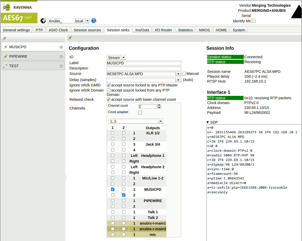
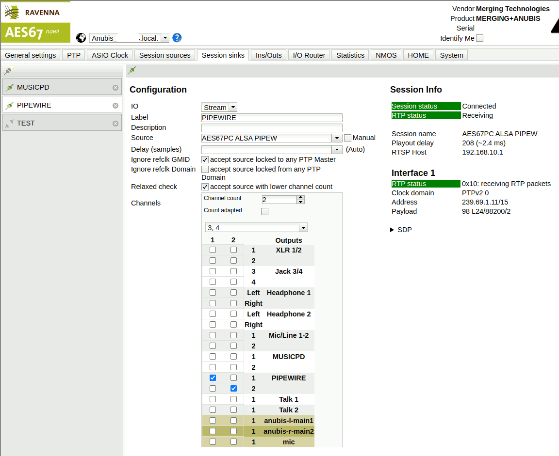
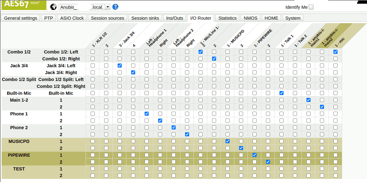
Without having thought about this usage in advance of buying the MERGING+ANUBIS this enables a use case that I had often wished to be possible: Mixing the PC sound outputs on an external/physical device. By the construction provided here, the granularity is very coarse (only MPD and PIPEWIRE to distinguish); but still this is already highly useful. E.g. when exploring new music, I often open it in a web browser and it may often times play louder than the regular music playback. Being able to offset the volume in the MERGING+ANUBIS is much more convenient than having to deal with a dedicated software mixer for such a purpose – usually, in the past, I didn’t even bother to use the software mixer and just changed the mains volume up and down…
Hardware Experience
This section contains some impressions from using the hardware of this setup. Although there are certainly also things to be said about the headphones, microphone and network switch, I focus on the AES67-enabled components here.
MERGING+ANUBIS SPS PRO
The MERGING+ANUBIS is a hell of an interface.
Analog properties are good (seems to be adequate for the high price). I was positively surprised to get a notable quality improvement on my (not really expensive) headphones compared to my previous interface (SSL 2). Reading from other reviews, the analog side seems to be on par with or exceed the capabilities of other expensive interfaces like the RME UCX II. The RME would have been my alternative choice for an interface upgrade if not for the AES67 technology and Linux support of the MERGING+ANUBIS.
Although from the outside, the number of inputs, outputs and user interface elements looks modest, the set of features and configuration offered through the touch screen graphical user interface is huge. Extensive studying of the various manuals (for the device itself, the missions and regarding proper AES67 configuration) is recommended.
Proper setup and operation is possible in Linux-only environments. No proprietary Windows software is required for the interface to work and all of the maintenance tasks like the AES67 setup and firmware updates can be performed through the web interface. I could not get to run the automatic sample rate switching yet, but it is highly likely to be a user error rather than a limitation of the interface’s Linux support. Also, there is some option to use Sound ID Reference for room correction which I think requires a Windows OS for performing the calibration measurements. Once the profile is created, it seems it could be uploaded and used without Windows, though.
While the MERGING+ANUBIS generally supports switching the sample rate to match the input source, this is not normally the case with other AES67 components (cf. the monitors below). Also, resampling is not supported by the interface. I think this is OK, but this was not easy to tell from the documentation in advance of buying. Maybe it would make for a good FAQ entry: “Does the MERGING+ANUBIS support resampling? No.” Then again, in the intended professional usage context of the interface, there is probably no demand for such a feature anyways.
The MERGING+ANUBIS contains an integrated active fan for cooling. In the settings, the threshold temperature for enabling this fan can be set to a high value (by setting the fan setting to LOW :) ) allowing for the fan to halt under standard temperature conditions. I chose to configure the Fan Cooling Mode to MID instead of LOW in an attempt to ensure maximum lifetime of the interface. When it turns on, the fan noise is noticeable and I don’t wholly agree with MERGING’s claim that it wouldn’t be noticable when used with a PC which also contains fans, because in audio environments there can be very silent PCs and then the fan may come out as an annoying noise. In my case, I have a standard (non-audio-optimized) PC making the fan audible but only as a faint additional sound in addition to the standard PC fan noise.
One thing that wasn’t easy to understand from the manuals in advance to buying the device is the concept of Missions. If the MERGING+ANUBIS were a PC, the missions might be thought of as multiple OS installations on the same PC: You can switch between them, but there is a “hard cut” (in the PC case: reboot) for doing so. Also, settings between missions are distinctive and don’t seem to influence each other. Even the AES67 configuration (e.g. sample rate) may vary between the different missions. This surprised me because from reading the manuals I would have expected the missions to be have like different views of the same device state but it seems each mission maintains their own configuration. In general, such a scheme is more flexible, but it depends on the use case whether this behaviour is actually helpful. In event that you sometimes want to use the MERGING+ANUBIS as a (portable!) mixing console and switch to the Music mission for that purpose but otherwise want to use it differently e.g. using the Monitoring mission, this is quite nice because you can store completely different device states for each mission. If you just want to quickly toggle the view depending on your use (all with the same connections and PC setup) e.g. switching between music listening and phone conferencing, the separation between the missions makes the initial setup much more complex and there is always a “hard” break between switching making it not a good choice for switching quickly between missions on demand. E.g. it is not really possible to switch from the Monitor to the Music mission just as someone is calling by a phone conference software or such.
By default, the Music and Monitoring mission are available. Both seem to be good user interfaces where MERGING got many details right for both of them.
The primary advantage of the Monitoring mission for music listening is the ability to configure (even complex) surround setups. Also, there is a very low latency in the volume control. Although I am a huge fan of having analog volume control dials, the MERGING+ANUBIS’ digital one is really nice to use in the monitoring mission.
The Music mission allows more advanced mixing to be configured on-screen. It also presents a view closer to what one would expect from a traditional mixing console i.e. there are some virtual faders displayed on the touch screen, individual channels can be muted and equalizer settings are just a touch away.
I personally configured to use the Monitoring mission for music listening, but I think it is effectively a matter of preference and such as long as no advanced surround capabilities are required, one may very well use the Music mission for listening, too.
The Neumann MT 48 is another interface which is very similar to the MERGING+ANUBIS but at sold a lower price. It provides USB and ADAT connections but limits the features on the software-side – it is basically “just” the Music mission). Most importantly for me, it doesn’t support Linux at all (known “not working”, see links below). It might be an interesting choice if you want to have the same AD/DA characteristics in a Windows setup and without the complexity of the AES67 network audio. Also, if anyone is adventurous to try it again on Linux, there may be a way by connecting to it via AES67 (instead of using it as an USB audio interface), but it from reading the manual it seemed as if this was not supposed to work either.
Reviews
- https://www.soundonsound.com/reviews/merginganubis
- https://audiophilestyle.com/ca/reviews/merging-technologies-anubis-on-the-desktop-r1084/ Note that here the reviewer actually broke a speaker due to bypassing the volume control of the interface in the AES67 connection settings (Aneman). Avoid this mistake by being ready to immediately stop the playback during testing and by considering sending software-side reduced signals (like 1% instead of 100% for a beginning).
- https://www.recordingmag.com/merging-technologies-merginganubis-music-mission/
- https://www.bonedo.de/artikel/merging-technologies-anubis-test/
MT48 not supported on Linux
The somewhat more expensive MERGING+ANUBIS works nicely, though…
- https://linuxmusicians.com/viewtopic.php?p=166481#p166481
- https://www.reddit.com/r/linuxaudio/comments/1ej68z2/neumann_mt_48_on_linux/
Manuals and Resources
All linked from https://www.merging.com/products/interfaces/downloads:
- https://www.merging.com/uploads/assets/Installers/Firmware/MERGING+ANUBIS%20User%20Manual.pdf
- https://www.merging.com/uploads/assets/Installers/Firmware/MUSIC+MISSION%20Appendix.pdf
- https://www.merging.com/uploads/assets/Installers/Firmware/SoundID%20Reference%20and%20Merging%20Anubis%20Guidelines.pdf
- https://www.merging.com/uploads/assets/Installers/ravenna/Configure%20Merging%20and%20AES67%20Devices.pdf
- https://www.merging.com/uploads/assets/Installers/ravenna/Merging%20Advanced%20Settings%20Guide.pdf
- https://merging.atlassian.net/wiki/spaces/PUBLICDOC/pages/4817447/Network+Switches+for+RAVENNA+-+AES67
Neumann KH 120 II AES67 W
The Neumann kH 120 II AES67 W is an active near-field studio monitor with DSP and digital input support. Apart from more common analog (XLR) and digital (coaxial S/PDIF) inputs this model can also directly play an AES67 stream. The monitor provides an analytical, neutral and clear sound signature.
The DSP features can be used to establish a room correction together with Neumann’s MA 1 Monitor Alignment software and the MA 1 measurement microphone. The MA 1 software is not available for Linux, but I managed to run it in a Windows VM in order to perform a Firmware Upgrade for the monitor.
When switched to AES67 mode, the monitor takes a significant time to start up (maybe about 2 minutes). The web interface allows configuring AES67 parameters. Sample rates 44.1kHz, 48kHz, 88.1kHz and 96kHz are supported in this mode, but the sample rate cannot be configured to automatically follow the source (unlike the MERGING+ANUBIS which has this feature).
Although the monitor exposes an API for volume control, it really looks as if it is only supposed to be used by the MA 1 software. When making use of the configuration through the switches on the back of the monitor, the volume control API is not available. In general it seems that volume control in AES67 setups is really expected to be performed in the digital domain.
After my first attempts at AES67 in aes67_audio_notes(37), I had configured the monitors to play at 96kHz sample rate (the maximum) and with the audio data directly supplied from the Linux PC, i.e. without the MERGING+ANUBIS as an intermediate. Back then, I noticed an occasional buzz sound from the monitor. This buzzing would be independent of whether some music was being played at the time or not and also always buzz at constant (max) volume. In the beginning, I thought this was an issue with AES67 timings and that the buzzing was an effect caused by the PC not running a proper real-time OS. I also suspected that maybe the use of the integrated clock source of the monitors was not the best choice. I thus switched to the analog input through the SSL 2 interface for some time. When I bought the MERGING+ANUBIS, I switched the monitors back to AES67. In the beginning there were no issues, but at some point the buzzing resumed. Having mostly ruled out the network latency and clock accuracy issues due to the use of a “proper” AES67-enabled device (MERGING+ANUBIS), I was wondering if one of the monitors might be defective.
As a final check prior to returning one, I exchanged the monitors’ positions (swapped the left and the right one). Afterwards, the buzzing would randomly occur from either of the monitors. I thus ruled out a defect of the individual monitor. During some online search I came across a person who noticed that they had buzzing interference at the monitor from a nearby WiFi router. Since the monitors are close to a wall with a different apartment on the other side, I suspect that it could indeed be related. This would explain why the issue would only occur randomly as it might depend on the actual data being sent via WiFi for the buzzing to trigger. Trying to find a solution around the issue, I experimented with the sample rate settings and interestingly, the buzzing would only occur at 96kHz but not at 44.1kHz nor 88.2kHz. I thus decided to switch the sample rate of the entire system to the 88.2kHz. The setup has since worked without any further buzzing issues.
In summary: When running in AES67 mode at 96kHz, the monitors are prone to interference, but changing any of these parameters (instead of AES67 use analog input or chose a different sample rate) fixed the problem for me. The hardware is not defective.
Reviews
- https://www.audiosciencereview.com/forum/index.php?threads/neumann-kh120-ii-monitor-review.46362/
- https://www.soundonsound.com/reviews/neumann-kh120-ii
- https://www.amazona.de/test-neumann-kh-120-ii-nahfeldmonitor-mit-dsp/
- https://www.soundandrecording.de/equipment/neumann-kh-120-ii-2-wege-nahfeldmonitor-im-test/
Manuals and Resources
https://www.neumann.com/de-de/serviceundsupport_de/downloads
Search for “KH 120 II AES67” and “KH 120 II”. Direct links to the official downloads seem to be hard to obtain.
About the Buzz Issue
The last entry was what hinted me towards considering the buzzing to be caused by external interference. Some other people had issues with the KH 120 [A] (not II) as a result of damaged PSUs that could be fixed by replacing capacitors.
- https://blog.fh-kaernten.at/ingmarsretro/2021/10/27/neumann-kh-120-mystery-noise-fix/?lang=en
- https://gearspace.com/board/so-much-gear-so-little-time/1156561-weird-noise-my-neumann-kh120a.html
- https://www.audiosciencereview.com/forum/index.php?threads/neumann-kh120-ii-monitor-review.46362/page-58
About Digital Audio Connectivity and Cables
When reading about digital audio connectivity, tons of acronyms are around. Although the focus of this article is certainly on AES67 which is quite friendly in terms of connectivity (its standard Gigabit Ethernet), some info was picked up about the alternative (mostly older) means for digital audio transmission.
Although AES67 may be the future, it may still make sense to build new (small) systems on top of the other alternatives since the equipment is often cheaper without any degradation of sound quality.
The following table provides an overview about the various digital audio connectivity options encountered while researching on AES67. In some special cases, the limits on channels and bit depth may be extended by choosing a special encoding format. Here, the audio is assumed to be entirely uncompressed PCM natively transmitted via the respective protocol
| Names | Connector | Channels | Sample rate/Hz | Bit depth | Voltage/V | Impedance/Ohm |
|---|---|---|---|---|---|---|
| AES3, AES/EBU | XLR | 4 | 384000 | 24 | 2.0–7.0 | 110 |
| AES3[-id] | BNC | 4 | 384000 | 24 | 1.0–1.2 | 75 |
| S/PDIF | RCA | 2 | 48000 | 20 | 0.5–0.6 | 75 |
| S/PDIF | TOSLINK | 2 | 48000 | 20 | n/a | n/a |
| ADAT | TOSLINK | 4/8 | 96000/48000 | 24 | n/a | n/a |
| MADI, AES10 | BNC | 14/64 | 96000/48000 | 24 | 0.6? | 75 |
| MADI | SC/optical | 14/64 | 96000/48000 | 24 | n/a | n/a |
- AES3 aka. AES/EBU
- Although it may sound similar to AES67, this is an entirely different approach: AES3 is a point-to-point connection transmitting two up to four channels over a single XLR or BNC cable.
- S/PDIF
- While the data format of S/PDIF is quite similar to AES3 to the extent that one can claim them to be compatible, the electrical and mechanical specifications differ. S/PDIF may run over the typical RCA connectors used for unbalanced audio connections in consumer equipment or alternatively be transmitted through an optical connector called TOSLINK.
- ADAT
- Although it also uses TOSLINK like S/PDIF, it is actually a different protocol intended to permit up to 8 channels at 48kHz or 4 channels at 96kHz.
- MADI
- From the non-AES67-based connection variants, MADI seems to be closest in terms of performance. It supports transmission of many channels over a single cable. It does not seem to be commonly available for connecting individual components like monitors, though.
References
- https://en.wikipedia.org/wiki/AES3
- https://www.soundonsound.com/glossary/aes3
- https://en.wikipedia.org/wiki/S/PDIF
- https://homerecording.com/bbs/threads/spdif-adat.393690/
- https://beta.prismsound.com/ufaqs/why-are-there-only-4-adat-channels-at-96khz/
- https://archiv.rme-audio.de/en/products/madi-center.php
- https://en.wikipedia.org/wiki/MADI
About Characteristic Impedance
- https://electronics.stackexchange.com/questions/93232/how-is-x%e2%84%a6-impedance-cable-defined/93236#93236
- https://www.allaboutcircuits.com/textbook/alternating-current/chpt-14/characteristic-impedance/
Fucture Directions
- Master the clocking issue by using the hardware clock of the Ethernet card. This may allow dynamic sample rate switching to work which could simplify matters and avoid resampling for headphone listening. Afterwards, when a working ptp4l setup exists, some exploartion could be made whether PipeWire might be able to receive/send AES67 directly i.e. bypassing ALSA and the need for a kernel module. Given that the ALSA-setup works quite nicely it seems it might be hard to beat by such a “simplified” setup.
- See if it is possible to hand an 8-channel ALSA device to PipeWire directly and then let MPD play through PipeWire in a bit-perfect manner to the first two channels (0+1) and send the remainder of the pipewire stuff to channels 2+3. This could remove the need for an explicit ALSA config file and makes ALSA behave like a “passive” component thus simplifying the setup in another (more production-ready?) way.
- Add a bass speaker (Neumann KH 750 DSP AES67) to the mix. -> Done, it works!
- Check options for room correction in the setup. There is at least SoundID Reference (expensive, but natively supported on the MERGING+ANUBIS) and Neumann MA 1 (natively supported by the speakers, but unclear if it can work with the intended Ethernet-only topology). -> According to Neumann support, almost all configurations that can be imagined can be made working. Specifically, MA1 correction can work in an all-AES67 workflow by configuring the 2.1 setup as “stereo” from Anubis point of view.
- Consider using a proper PoE-capable switch, maybe replacing the existing setup with dedicated switches for home and audio networks with one switch that is partitioned into multiple logical groups for audio and home networking respectively.
- Explore the possibility to create an own USB-to-AES67 sound card. The code and some basic documentation about this is already there: https://github.com/bondagit/aes67-linux-daemon/blob/master/USB_GADGET.md What is missing is a sensible choice of hardware and RT-optimized Linux OS to run this thing in a plug-and-play manner.
- Experiment with other ALSA plugins than
plugbecause this one is too powerful e.g. supports integrated sample rate conversion which is to be avoided when pursuing the best quality signal path from file to ear.
See Also
Previous article in this series: aes67_audio_notes(37).
Repositories with build instructions and config files:
Repositories with softare components:
Practical Guide to AES67 (very useful): https://www.ravenna-network.com/your-practical-guide-to-aes67-part-2-2/.
39C3 had a talk about PTPv2 time sync. It gives a very good introduction into the time synchronization via PTPv2 and uses an ARISTA 710P-16P, MEINBERG microSync (TM) and Merging Anubis for demonstration: https://ffmuc.media.ccc.de/congress/2025/av1-hd/39c3-1832-eng-deu-fra-Excuse_me_what_precise_time_is_It_av1-hd.webm